Monthly Archives: November 2010

The Following posts

The following posts were originally part of a website called MathsYear2000 which was created that year by the UK Department of Education.

The site was changed to http://www.Counton.org which, because of lack of funding is a shadow of its former sense.


Sliceforms – the background

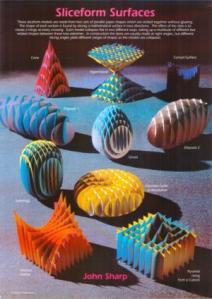
Sliceform models are three-dimensional objects created by slicing a solid many times in two directions. The models are a series of cross sections which are made of a set of planes cut from card slotted together.

Most Sliceforms are continuously deformable from the extremes of two flat shapes which form interesting designs in themselves. The intersections of the slices act as hinges.

The pictures you see here do not show their full beauty. You have to make them and play with their endless shapes and see the way light plays on them as you move them about and deform them. As you move the Sliceforms they change colour dramatically at times. This is apart from the constantly varying and interesting shadows they cast.

Who invented Sliceforms?
The Sliceform technique originated with a mathematician called Olaus Henrici who taught in London at the end of the nineteenth and early twentieth centuries. He made models using cross sections of quartic surfaces; these are similar to a sphere but have with cross sections which are ellipses, hyperbolae or parabolae.

Models were constructed for sale in Germany by the firm of Martin Schilling. These were designed by Alexander von Brill in Darmstadt.
The method for making the models has not been fully exploited, although it has been used for making packing for fruit and other small regular items.

In the nineteenth century mathematical models were made for teaching and understanding geometry. Many museums have collections of these.

The Strange Surfaces exhibition at the Science Museum in London contains Sliceforms from the 19th century to the present day (by Brill and John Sharp)  and other interesting historical models of surfaces. Visit their website for more details.

John Sharp has extended the system to a wide range of surfaces and polyhedra, under the name Sliceforms.

Ten minute Sliceforms

See also the post How to make and assemble the models and Sliceform templates and Downloads

The following models are simple ones for you to learn to assemble the models.
In many cases there are more detailed versions or variations which take longer to cut out and assemble because they have more slices.

These models take about ten minutes each to make.

Do not think that because they take such a short time to make that they are any less interesting or complicated to make.

Try them first before you make the more advanced models.

Possible explorations
Use them to explore variations with different coloured sets of slices.
Can you make right and left handed versions by colouring?
What types of symmetry do they have?

The models

More advanced Sliceforms

See also  the post on how to make and assemble the models and Sliceform templates and Downloads

The following models are either more advanced versions of the Ten minute Sliceforms or ones with many slices comparable to the ones in John Sharp’s Sliceform book.

These models take about an hour to each to cut out and assemble, depending on how experienced you are.

Even if you have made Sliceforms before, try the Ten minute Sliceforms before you make the more advanced models. In most cases having the simple version to hand will help you when you come to make the more advanced ones.

The models

Books and Poster on Sliceforms

John Sharp has two books on Sliceforms published by Tarquin.

Sliceforms


Sliceforms is a set of eight models to cut out and make.
The models in the book have similar numbers of slices to the advanced models described here.  There is a short description of creation of models.

Surfaces: Explorations with Sliceforms

Surfaces is a more advanced book. It describes various techniques for creating Sliceforms from purely artistic methods to mathematical ways of modelling surfaces using this technique.

Sliceforms Poster

The Sliceforms Poster is available as thick paper and also in a laminated version.

CLICK ON THE LINKS ABOVE TO GO TO THE TARQUIN SITE TO ORDER THEM


How to make and assemble the models

Please read the following instructions carefully, especially the way to cut the slots. If you just cut slits, with a single cut instead of a slot as described below, then the model will buckle and will not deform properly. The following results compare well cut slots on the left with the effect of only cutting slits on the right.

How the templates are provided

Templates for each model are provided as files to print. You can either print directly onto card or print and then photocopy.

Files are provided as Adobe Acrobat PDFs

The reason for supplying files like this, rather than presenting them as web pages is to get good quality fine lines. To show them as good enough quality would mean large files that take a long time to download. Also the line thickness has been adjusted so that, when you cut out the slices, you leave the minimum construction line on the model.

This way you can have files ready to print at any time, or prepare masters for classroom teaching.

Printing or copying onto card

The templates are for printing or copying onto photocopy card (160 gsm).
The page size of the model is A4 or US letter size. Make sure you select the correct template for the page you are using.
Many simple models can fit onto to a single page so templates are provided for making many models from the same sheet of card, for example for classroom teaching, or a sheet is provided with more than one model.

The larger models with more slices are designed to print on two sheets of card. In some cases the slices are the same on both sheets, whereas for others the two sheets are different. Please read the instructions for each model.

With the larger models, use different colours of card for the two sheets. By making copies on two cards and using one colour in each direction, you will get much better models; they are also easier to make.

Do not try to enlarge the models, they will not work as well.

Cutting out the slices and cutting the slots

When you cut out the slices, cut just inside the line so there is no drawn line visible on the final model.

In most cases it is best to cut out one or two slices at a time, then cut the slots and then assemble them. Some templates have numbered tabs to show you the order of the slice. Cut these off when the model as been assembled.

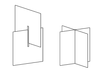
It is very important that you cut slots and not just slits. You must cut just enough for the card making the slice to fit neatly in the slot. If the slot is too much wider, the model is likely to fall apart easily, especially in the early stages of assembly. If you just cut a slit along the line, then the forces acting sideways on the slices will cause the model to buckle. Slots look like this:

Cut the slot with scissors making a pair of cuts either side of the line. This will give a sliver of card which will often curl up like a hair. Pinch it off at the end of the slot by grasping it with your fingernails.

To practice cutting slots, use some spare card from the edge of the template with a short pencil line drawn on them.

A Sliceform tetrahedron

See also the posts on how to make and assemble the models and Sliceform templates and Downloads

This Sliceform is available in two versions, a simple one which takes about 10 minutes to cut out and assemble since it has only six slices and a more advanced one which has 18 slices and takes about an hour to make.

You should make the 10 minute one before attempting the advanced one.

How the model is designed

This model has been designed by taking a tetrahedron in a cube like this:

and making two sets of slices, one horizontal and one vertical, parallel to sides of the cube.

These slices are all rectangles. See at the end of the post  for why. It should help you to assemble the tetrahedron Sliceform.

The 10 minute tetrahedron template

Download the file you want for printing and use that to create the model. The following graphic is to help you understand what the slices look like.

The slices for half of the model look like this:

A single page of the template contains slices to make four tetrahedra. Make two copies, each on different coloured card and mix the different coloured slices for different effects, to give eight variations on the tetrahedron. Start by making all slices in each direction a different colour.
See How to make and assemble the models for general printing instructions for printing or copying onto card.

Assembling the 10 minute tetrahedron

See the post on how to make and assemble the models for more about cutting out and cutting the slots. Take extra care with the slots.

The simple model only has six slices. The two central squares that correspond to the squares in the design model and two other slices in each direction.

Since there are only a few slices, cut out all the pieces and cut the slots on each one.

Fit the centre squares together, then add the other two slices in each direction. Use the two half tetrahedron models to judge how they are orientated. Think symmetrically.

When you have made the model, fold it flat in two directions.

The advanced tetrahedron template

Download the file you want for printing and use that to create the model. The following graphic is to help you understand what the slices look like.

The slices for half of the model look like this:

A single page of the template contains slices to make one tetrahedra. Make two copies, each on different coloured card and use one colour in each direction to make two models.

See the post on how to make and assemble the models and Sliceform templates and Downloads for the general instructions for printing or copying onto card.

Assembling the advanced tetrahedron model

This model has many more pieces and takes up to an hour to make. With more slices the tetrahedron looks more solid.

Make the simple model first so that you can see the structure when you are making this one.

Take extra care not to cut the slots too wide or you will find that the pieces fall out in the early stages of assembly. You will probably find it easier to cut pairs of slices and then fit them onto the model.

Cut out the central squares and their slots and fit them together. Then cut the next four slices (two in each direction) and add them to your model. Continue cutting and adding four slices at a time until you reach the outside. If you make the model with two colours of card it will not only be a more interesting model, it will also be easier to make.

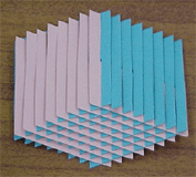
When you have made the model, fold it flat in two directions. With it folded, tap the long flat ends gently on a flat surface to distribute the slices evenly in the slots. Look at the patterns it creates.

The slices of a tetrahedron and why they are rectangles

This is a picture of a conventional net for half a tetrahedron.

Cut two versions out on paper and assemble them by sticking the tabs.

Placing the squares of the two halves together makes a tetrahedron (if you put them together with a 90 degree rotation).

The dotted lines show the position of slices for making the Sliceform.
Measure them and trace them round to see how the shapes of the rectangles change, from a long thin one at the edge, to a fatter one as the sides become equal in the central square. As you continue to the other half, they become longer and thinner again, but in the other direction.

It is a good idea to make this model to help you see how the rectangles of the Sliceform slot together.

A Sliceform Zonohedron

See also the posts on how to make and assemble the models and Sliceform templates and Downloads

This Sliceform is available in two versions, a simple one which takes about 10 minutes to cut out and assemble since it has only six slices and a more advanced one which has 16 slices and takes about an hour to make. They are both made of the same shaped slice, and all slices are the same.

You should make the 10 minute one before attempting the advanced one.

How the model is designed

If you make a cube from drinking straws, connecting the straws with string threaded through them, then the cube is all floppy. If you distort it so that sides of the cube remain parallel by pulling two opposite corners away from one another, then you create a zonohedron. This is a rhombic prism and is the simplest of the zonohedra.

Questions

  1. In this model all the faces of the zonohedron are identical. Do they have to be in a zonohedron?
  2. The model is made up of identical slices, not only in shape but in the way the slots are cut. Why is there only one template slice required when the slots point up in one direction and down in the other?
  3. Which Archimedean polyhedra are zonohedra?

The zonohedron templates

Download the file you want for printing and use that to create the model. The following graphic is to help you understand what the slices look like in each model.

Each slice looks the same. The only difference in the two models is that the simple one, because it has only has six slices, has three slots in each slice and the advanced one has nine. There are two ways the slots are cut in the simple model. For the central slices they are not all on the same side. This helps to keep the slices from fallling out:

A single page of the 10 minute zonohedron template contains slices to make four models.

A single page of the advanced zonohedron template contains slices to make one model.

See the post on how to make and assemble the models for more about printing or copying onto card.

Make copies on different coloured card and make all slices in each direction a different colour.

Assembling the 10 minute zonohedron

See the post on how to make and assemble the models for details about cutting out and cutting the slots. Take extra care with the slots.

Since there are only a few slices, cut out all the pieces and cut the slots on each one.

The simple model only has six slices. Start with the two slices that have opposite slots in the centre. These are the central slices. Then add the two outside pairs of slices in each direction, making sure that you insert them the same way as the central ones in each direction.

When you have made the model, fold it flat in two directions.

Assembling the advanced zonohedron

This model has many more pieces and takes up to an hour to make. With more slices the zonohedron looks more solid and it generates more interesting patterns when it is flattened.

Make the simple model first so that you can see the structure when you are making this one.

Take extra care not to cut the slots too wide or you will find that the pieces fall out in the early stages of assembly. You will probably find it easier to cut pairs of slices and then fit them onto the model.

All slices are identical, so cut any two out and their slots and fit them together. Count along the slots to fit the fourth slots together symmetrically. Then cut the next four slices (two in each direction) and add them to your model. Continue cutting and adding four slices at time until you reach the outside. If you make the model with two colours of card it will not only be a more interesting model, it will also be easier to make.

When you have made the model, fold it flat in two directions. With it folded, tap the long flat ends gently on a flat surface to distribute the slices evenly in the slots. Look at the patterns it creates.

Activities

  1. Create your own zonohedra with different shaped rhombi. You could make a number of ones like the simple, 10 minute, one or you could work as a group in a class or with your friends with the advanced one.
  2. When you have the set, compare the shapes and patterns they make when they are flattened. What is the relationship between the shape and the angle of the rhombus?
  3. With the simple (10 minute) one, investigate possibilities using mixtures of colours.

A Sliceform hyperbolic paraboloid

See also the posts on how to make and assemble the models and Sliceform templates and Downloads

This Sliceform surface is available in two versions, a simple one which takes about 10 minutes to cut out and assemble since it has only six slices and a more advanced one which has 16 slices and takes about an hour to make. They are variations on the hyperbolic paraboloid and not different versions of the same model. The advanced one is a skew hyperbolic paraboloid based on the zonohedron Sliceform model.

What is a hyperbolic paraboloid?

This is a surface which is shaped like a saddle.
If you intersect the surface with three perpendicular planes, in two directions the curve you see on the plane is a parabola, and in the other it is a hyperbola.

A parabola is a common curve which can be drawn using a set of tangents (that is drawn as its envelope). It is commonly seen in curve stitching.

If you look at the pictures of the models above, a parabola is clearly visible. A hyperbola is obtained by cutting the surface horizontally.

It is not surprising that a hyperbolic paraboloid (which is a three dimensional surface) can be created using a type of curve stitching in space. A surface that is made from a series of lines is called a ruled surface.

The simple, 10-minute Sliceform hyperbolic paraboloid is formed as a ruled surface by taking two lines on opposite faces of a cube and dividing them into an equal number of parts. These lines are different non-parallel diagonals of the faces and are known as skew lines because they can never meet in space.

The lines are joined starting by joining A and H and then moving from A to F and joining a corresponding point on H to C so that the final points joined are F and C. This gives the surface like this:

This is a stereoscopic pair (a bit like the 3D posters which were popular a few years ago). If you stare at the image and cross your eyes slightly, so that a third image appears between the two of them, then you will see the three dimensional version of the ruled surface.

If you use a similar set of lines using the two skew lines formed by joining from the points A and H and from F and C, amazingly, the lines lie in the same surface.

If you look at the ruled surface from an edge of a cube, it looks like this:

Not only can you see the parabola, but the lines make it look as if it is a curve stitched one.

How the models are designed

The simple, 10-minute Sliceform hyperbolic paraboloid is formed from a cube by making slices parallel to the vertical faces of the cube, through the ruled lines of the surface.
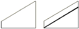
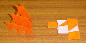
This gives a set of slices like the one at the left. Part of this slice is then cut off, as shown at the right to give the slice for the Sliceform.

For the advanced model, a zonohedron is the starting point instead of using a cube. For this model, the complete slices are used, not a cut down version as with the simple one.

The 10 minute hyperbolic paraboloid template

Download the file you want for printing and use that to create the model. The following graphic is to help you understand what the slices look like.

The slices for half of the model look like this:

See the post on how to make and assemble the models for more about printing or copying onto card.

Assembling the 10 minute hyperbolic paraboloid

See the post on how to make and assemble the models for more about cutting out and cutting the slots. Take extra care with the slots.

Since there are only a few slices, cut out all the pieces and cut the slots on each one.

The simple model only has six slices. In each direction there is a rectangular slice, which is the central one in each direction. In the ruled surface diagram, this corresponds to the line joining the centre points of the lines on opposite faces of the cube.

Fit the centre rectangles together, then add one slice in each direction as follows.

When you fit slices like this, always ensure that the “corners” of the top part fit together symmetrically like a butterfly opening its wings as at the top of this diagram.

The slots are cut so as to weave the slices together. This stops the slices falling apart when you have assembled them all.

When you have made the model, fold it flat in two directions.

Activities

The following are some ideas to explore:

  1. How many different versions of the model can you make by varying the colours?
  2. Is it possible to make versions that are mirror images of one another?
  3. What is the relationship of the model to the tetetrahedron?

The advanced skew hyperbolic paraboloid template

Download the file you want for printing and use that to create the model. The following graphic is to help you understand what the slices look like.

Two slices for each half of the model look like this:

In the top one, all the slots come up from the bottom and in the lower one they are all from the top. Note also that there are numbered tabs to identify the slice while you are assembling it. These tabs should be removed when the model is complete. As well as showing the order for the slices, they also show which way round it fits in the model.

Assembling the advanced skew hyperbolic paraboloid

See the post on how to make and assemble the models for more about cutting out and cutting the slots. Take extra care with the slots.

There are 16 slices. Although you can cut them out before assembly, since they are numbered, it is easier to cut pairs and then assemble them.

For this model, work in pairs with slices from 1 to 8. Fit the smallest slots in both slices numbered 1 together, then add both numbered 2, keeping the tabs in the same direction.

When you have assembled the model, fold it flat in two directions. You might find that it resists to start with and then suddenly jumps flat. When it is folded so that you have a flat base, hold it between your thumb and forefinger and tap it gently on the flat base to bring the slices together evenly.

When you open it out, the tabs stick out and can be cut off.

When you flatten the model, without the tabs, one way is similar on both sides:

But the other way it is not, and then you can see the parabola showing different “designs” when you turn it over.

The parabola is obvious when the model is open also

A Sliceform Super-egg

See also: the posts on how to make and assemble the models and Sliceform templates and Downloads

This Sliceform surface is only available in one version, with 18 slices and takes about an hour to make. It is called a super-egg, but it is really a surface of revolution called a super-ellipsoid.

What is a Super-ellipsoid?

A superellipsoid is a surface of revolution of a super-ellipse. So what is a super-ellipse and what is a surface of revolution?

A surface of revolution is a surface formed when you take a curve and rotate it in space about a line (the axis of revolution).

  • So if you rotate a circle about a diameter as axis you get a sphere.
  • If you rotate a line about an axis which is parallel to the line, then you get a cylinder.
  • If you rotate a line about an axis which intersects the line then you get a cone. This means that the cylinder in the example above can be considered as a very special cone. Similarly, if the angle of intersection of the axis and the line is 90¡ then you get a plane.

A super-ellipse is a special curve which can look like an ellipse or it can take a variety of other shapes. The reason it is called is super-ellipse is because its equation is obtained by modification of the equation of an ellipse.

This is the shape of the super-ellipse used for making the super-ellipsoid as a surface of rotation.

Note how the shape is more rectangular than a true ellipse.

The super-ellipsoid formed when this particular super-ellipse is rotated about its long axis has been used to create the Sliceform.

What’s special about this super-ellipsoid?

This shape super-ellipse was chosen to make a super-ellipsoid by the Danish scientist, designer, inventor and poet Piet Hein (1905-1996). He called it a super-egg because of the way it balances on both ends with a kind of spooky stability.

See below for more about the super-ellipse and the inventor of the super-ellipsoid, Piet Hein including links to other web pages and to find out what is special about this super-ellipsoid.

The super-egg templates

Download the file (in the templates post below) you want for printing and use that to create the model. The following graphic is to help you understand what the slices look like in each model.

Remember, they are slices and not necessarily super-ellipses.

There is only one page of template, since the super-egg’s symmetry means that the templates in each direction are the same. One set is upside down compared to the other.

Assembling the Super-egg Sliceform

See the general instructions post on assembling Sliceforms for cutting out and cutting the slots. Take extra care with the slots.

There are 18 slices. In each direction, the largest slices are in the centre. Begin by assembling these, then fit the next smaller size either side and so on until you reach the outside.

When the model is assembled it folds flat to give the same pattern in both directions:

Since it is not solid, it does not have the same stability problems as a “real” super-egg, but it will balance in many different ways:

Piet Hein and the Super-ellipsoid

Problems worthy
of attack
prove their worth
by hitting back.
PIET HEIN

This is one of Piet Hein’s poems which he called grocks (or grucks in Danish). They are short poems with his own brand of humour which also have a wise overtone. You can find more about them in the links below.

The origin of the super-ellipse

Piet Hein did not discover the super-ellipse. That honour goes to the French mathematician Lamé who took the equation for the ellipse and asked “what if?” it was part of a wider set of curves.

The equation for the ellipse is:

Lamé wrote the equation as:

and asked what the curve would like if n was not equal to 2 but took on other values.

If n is zero then the curve becomes a pair of crossed lines. As it increases so the curve changes from being a curved star shape (you may recognise a curve called an astroid) to a rectangle with diagonals a and b when n equals 1.

Between 1 and 2 the curve turns from a curved rectangle towards an ellipse. It is an ellipse with major and minor axes a and b when n equals 2.

When n goes above 2, the curves starts to look interesting even more interesting. It becomes a rounded rectangle.


Piet Hein’s use of the super-ellipse

Piet Hein used the super-ellipse with values of n greater than 2 for designing. He made roundabouts in roads and desks and tables with this shape.

Then he took the super-ellipse with a ratio of a:b of 4/3 and with n equal to 2.5 and created a surface of revolution to give the super-ellipse used in this Sliceform model.

More about Piet Hein

You can find out more about Piet Hein with the following links, but one of the best descriptions is in Martin Gardner’s book “Mathematical Carnival”.

Notes on Piet Hein

Brief biography of Piet Hein
Piet Hein and the Soma cube
Piet Hein’s board game, Hex and here
Superellipse and Superellipsoid